

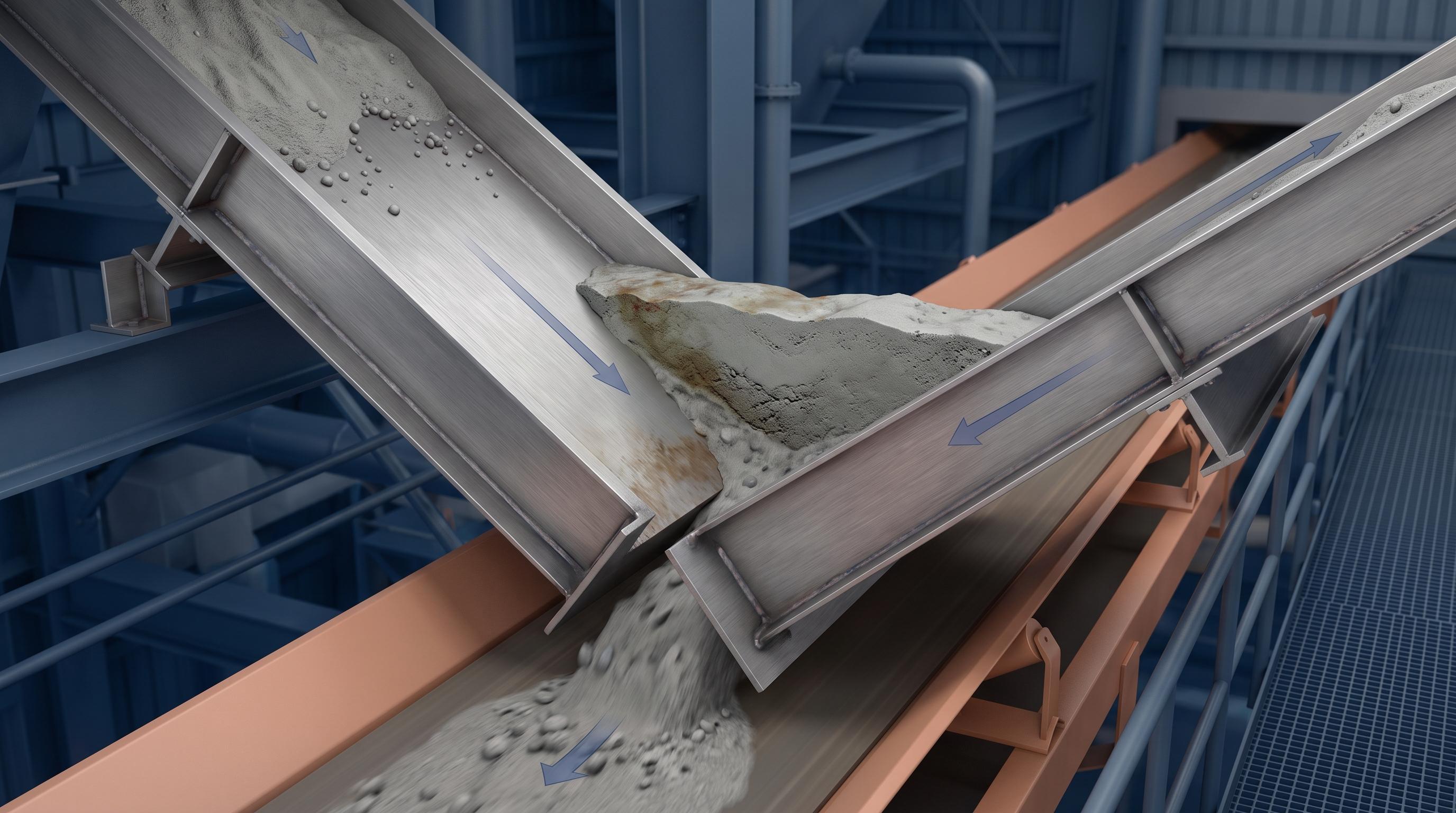
Material builds up in a transfer chute corner because the valley angle is always shallower than the chute plates that create it. A chute can look steep on the drawing and still have a corner that is too flat to keep material moving.
That is why two plates set at 55° produce a valley of only 45°. If your material needs more than 45° to keep sliding on that liner, it will stop in the corner first, even while the flat walls stay clean.
So the answer is simple: buildup starts when the valley fails the material’s minimum slope, not when the plate angle looks wrong. The fix is to calculate the valley, compare it with wall friction for the actual liner, and design the corner, not just the walls, to clear it.
Quick check: cot²(valley) = cot²(A) + cot²(B). Two 55° plates give a 45° valley. Two 60° plates give 51°. If you need a 60° valley, the plates have to be about 68°. Design to the valley, not to the plate.
It is the angle of the line where two sloping surfaces meet, measured from horizontal.
Picture a chute corner. The back plate slopes down at one angle. The side plate slopes down at another. Where they join, they form a line running down into the corner. The slope of that line is the valley angle.
Material does not slide down the plate. It slides down the steepest available path, and in a corner that path is the valley. So the valley is what has to be steep enough, not the plates you drew.
Some drawings call it the gully angle. In US plants, valley angle is the term you will hear.
Because the corner is the flattest part of a chute that looks steep everywhere else.
Material needs a minimum slope to keep moving. Below that slope it stops. When the plates clear that minimum but the valley does not, you get exactly what most plants see:
Flat walls stay clean
Corners collect material
The buildup narrows the opening
Flow gets pushed to one side
The chute eventually plugs
The frustrating part is that the drawing checks out. Someone specified 55° walls for a material that needs 45°, and the walls are fine. Nobody calculated the corner.
Field note: In retrofit work, this is a common failure pattern. The plant asks for a liner change because the corner is packing up, but the real issue is often the valley itself. The walls look steep enough, the wear looks manageable, and the corner still loads because nobody checked the valley against the actual material-liner pair.
Why the geometry matters operationally: unplanned downtime is one of the most expensive problems in bulk handling, and an unplanned production stoppage routinely costs far more than the cleanup that follows it. When a chute corner starts holding material, the cost is not just cleanup, it is lost production time.
Use the two plate angles. The formula is:
cot²(valley) = cot²(plate A) + cot²(plate B)
Both plate angles are measured from horizontal. Solve for the valley.
Here is what it gives you when both plates sit at the same angle:
Both plates at | Valley angle |
|---|---|
50° | 40° |
55° | 45° |
60° | 51° |
65° | 57° |
70° | 63° |
75° | 69° |
Read the 55° row again. The valley is 10° shallower than the plates. That gap does not close as you go steeper. At 75° plates you still lose about 6° in the corner.
Now run it backwards, which is how you should actually use it. For a 60° valley set the plates at about 68°. For a 65° valley set them at about 72°. That is the number to put on the drawing.
The spec sheet has our standard chute geometry and liner options if you want to check a design against real builds.
There is no single number, and any answer that gives you one is guessing.
The minimum comes from your material, not from a rule of thumb. What sets it is the wall friction angle between your material and the liner you are using. The valley has to be steeper than that, with margin.
What holds in practice:
Free-flowing dry material usually moves on a valley around 60°
Cohesive or damp material often needs 65° to 70° or more in the valley
Sticky material can need more than any practical plate angle, which is a signal to change the liner or the geometry rather than chase degrees
Notice all three are stated as valley angles. Convert them back to plate angles with the table above before you draw anything.
These three get used interchangeably. They are not the same, and only one of them belongs in your chute calculation.
Term | What it measures | Use it for |
|---|---|---|
Valley angle | Slope of the corner between two plates | The number your chute has to clear |
Wall friction angle | Friction between the material and the liner surface | Setting the minimum slope you need |
Angle of repose | Slope a pile forms when you dump material on the ground | Stockpiles and hoppers, not chute walls |
Angle of repose is the one that causes trouble. It gets quoted in chute specs constantly, and it tells you nothing about how material behaves against a steel or ceramic wall. Wall friction is what governs, and it changes when you change the liner.
Switching from AR400 to UHMW-PE lowers the wall friction, which lowers the slope you need. The liner and the geometry are one decision, not two.
The cleanest fix is to not have a valley at all.
Four ways, roughly in order of how well they work:
Round the corner. A radiused valley gives material no flat line to rest on. This is the best answer where you have room to build it.
Steepen the plates. Use the table above and design to the valley you need. Simple, but it costs headroom.
Make the side walls vertical. No slope on the side means no valley to form. Works where the chute is narrow enough.
Chamfer the corner. A flat plate across the corner turns one shallow valley into two steeper ones. A retrofit answer more than a design one.
We build transfer chutes with DEM-modelled geometry for exactly this reason. The corner is where the model earns its cost, because it is the part hardest to judge by eye.
The geometry rule does not change. The liner and the required angle do.
Material | Liner | Notes on the valley |
|---|---|---|
Clinker | Ceramic tile | Hot and highly abrasive. Ceramic gives 3 to 5 times the wear life of AR steel here. Low wall friction helps the corner. |
Coal | AR400 or AR500 | Wall friction climbs with surface moisture, so design for the wettest coal you run, not the average. |
Fly ash | UHMW-PE | Low abrasion, low friction. Fine and light, so it packs into a shallow corner easily. |
Limestone, raw meal | AR400 or UHMW-PE | Moisture-sensitive. The angle that worked dry will not work damp. |
Along the Gulf Coast and through the Southeast, humidity sits at 70 to 90 percent for months. Coal, raw meal, and limestone all pick up surface moisture, wall friction climbs with it, and a valley angle that ran clean through winter starts holding material in August. Design the corner for the worst month, not the sample you happened to test.
Temperature sets the liner too. Standard chute builds run to about 176°F. Clinker cooler discharge and hot transfers need high-temperature designs, which we rate to about 392°F with AR400 or ceramic.
Use the table for a straight two-plate corner. Use DEM when the corner is not simple.
DEM, or Discrete Element Method, models the material as individual particles and shows you where the stream actually goes. It is worth the cost when:
The chute is curved, hooded, or spooned rather than straight plates
Material lands off-center and loads one corner harder
The transfer feeds a belt at an angle
You have already rebuilt the chute once and it plugged again
For a plain corner on free-flowing material, the formula is enough. Reach for the model when the geometry stops being two flat plates.
Our chute designs are DEM-validated and engineered to CEMA guidelines, and the corners are usually where the simulation changes what we would have drawn by hand.
Deployment note: On site, the corner usually shows the problem before the rest of the chute does. You see packing at one edge, cleanup crews start clearing the same spot each shift, and the flow line begins to drift. That is often the point where a quick valley check or DEM review prevents another rebuild.
Most of the chutes we are asked to re-line have the same story. The walls are fine. The corners are packed. The drawing was checked against the plate angle and nobody ran the valley.
It is a five-minute calculation at the design stage and a shutdown once it is built.
If you have a chute plugging in the corners, or a new transfer where the headroom is tight, our engineers can run the valley angle against your material and liner and tell you what the plates need to be.
The valley angle is always shallower than the plates. Two 55° plates give a 45° valley.
Calculate it with cot²(valley) = cot²(A) + cot²(B), then design to the valley, not the plate.
A 60° valley needs plates at about 68°. A 65° valley needs about 72°.
Wall friction sets the angle you need. Angle of repose does not belong in a chute calculation.
Rounding the corner beats steepening it, where you have the room to build it.
It is the slope of the line where two chute plates meet, measured from horizontal. It is always shallower than either plate that forms it. Material slides down the steepest available path, and in a corner that path is the valley, so the valley is the angle that has to clear your material's minimum, not the plate angle on the drawing.
Use cot²(valley) = cot²(plate A) + cot²(plate B), with both plate angles measured from horizontal. For two plates at the same angle, 55° gives a 45° valley, 60° gives 51°, 65° gives 57°, and 70° gives 63°. Run it backwards to design: a 60° valley needs plates at about 68°.
Because the corner is shallower than the walls. If the plates clear your material's minimum slope but the valley does not, material keeps moving on the flat surfaces and stops in the corner. The buildup then narrows the opening and pushes flow to one side.
It depends on the wall friction between your material and your liner, so there is no universal number. Free-flowing dry material generally moves on a valley around 60°. Cohesive or damp material often needs 65° to 70° or more. Those are valley angles, so convert them to plate angles before drawing.
No, and using it will mislead you. Angle of repose is the slope a pile forms when material is dumped on the ground. It says nothing about how that material behaves against a steel or ceramic wall. Wall friction angle is what governs chute design, and it changes when you change the liner.
Remove the valley or make it steeper. A radiused corner is the best answer because material has no flat line to rest on. Steepening both plates works but costs headroom. Vertical side walls remove the valley entirely on narrow chutes. A chamfer across the corner is a retrofit option that turns one shallow valley into two steeper ones.
Not for a straight two-plate corner on free-flowing material, where the formula is enough. DEM earns its cost when the chute is curved, hooded, or spooned, when material lands off-center and loads one corner harder, or when a rebuilt chute plugged again and you need to see where the stream is actually going.

Delivering advanced conveyor solutions from Houston across the U.S.


